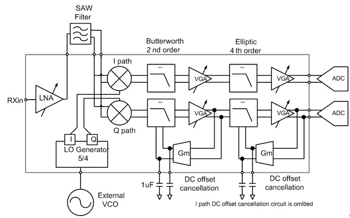
Implemented W-CDMA Direct Conversion Receiver Block Diagram
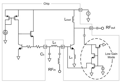
LNA
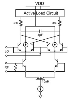
Mixer
|
Implemented W-CDMA Direct Conversion Receiver Block Diagram
|
|
|
LNA
|
Mixer
|
|
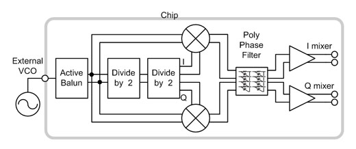
IQ Generator
|
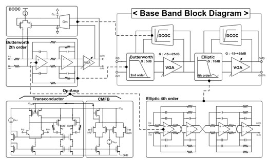
Baseband Block diagram and
Filter
|
|
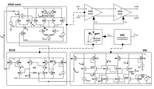
VGA
|
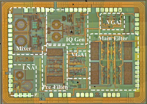
Chip Photograph
|
|
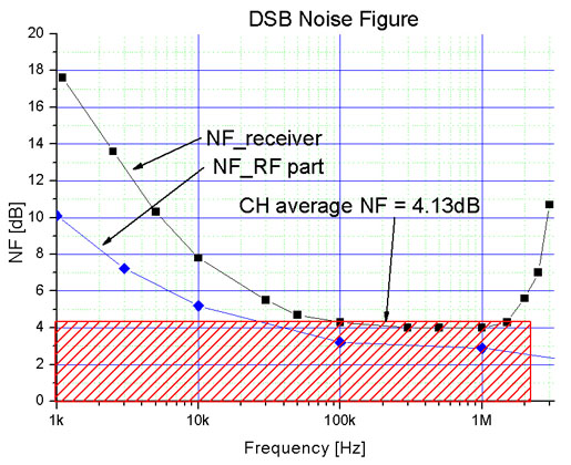
Noise Figure of the
Receiver
|
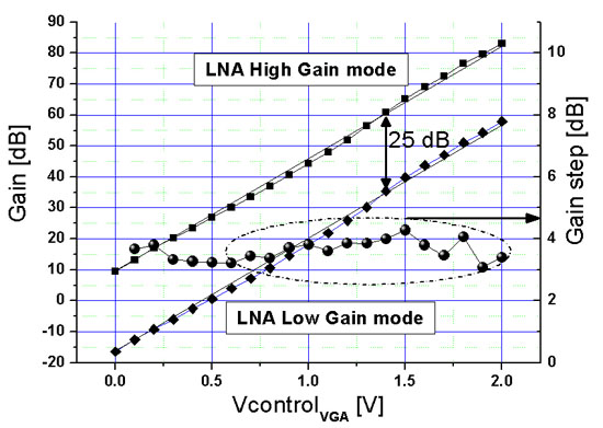
Gain variation and gain
step error
|
|
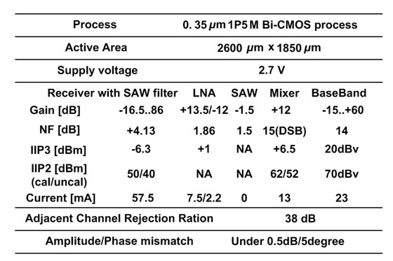
Receiver Performance
|
|