1.
Digital Predistortion Techniques
In
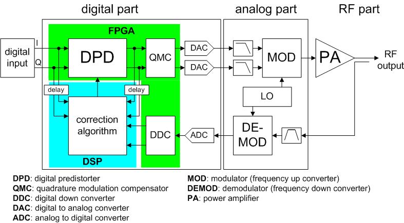
digital domain, it is possible to represent distortion characteristics of power
amplifier more accurately. So the linearization performance of digital
predistortion technique is superior to analog one. Research of digital
predistortion is in progress. Following figure shows the configuration of
digital predistortion using DSP and direct IQ mod/demodulator.
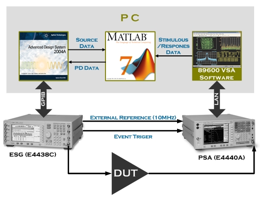
For
experimental demonstration, we
use the test setup as shown. The digital signal processing core is substituted by personal computer (PC) with the MATLAB software. The
Agilent’s ESG (E4438C) and PSA (E4440A) are used for a
generation of PD signal and a collection of PA response by use of ADS and VSA
software for the communications with PC.
2.
Adaptive Digital Feedback Predistortion (DFBPD) Technique
The
analog feedback predistortion (FBPD) linearization method can accurately
extract the PD signl and enhance the tolerance of the intermodulation distortion
cancellation by the feedvack linearization. However, the critical problems
of FBPD are the operation at bandwidth limitation caused by the loop delay,
and an oscillation tendency caused by the feedback technique. By employing
a digital LUT technique, these limitations can be overcome, while maintaining
the advantages of the feedback circuit. Moreover, FBPD can enjoy the abundant
merits of the DPD. In the linearizeer, the main signal, as well as the error,
aaree fed back, suppressing the open loop gain. We believe that this is
the first report of PA linearization using PD aand feedback techniques together
in the digital domain, which eliminates the problems of the RF feedback
circuit. As result, the distortion correction of the PD is carried
out by the DPD and further enhanced by the feedback linearization. Compared
to conventional DPD, the IM cancellation tolerance is enhanced by
a factor of the gain compression of the feedback circuit, and ther error
extraaction algorithm is very simple.
2.1
Operation of DFBPD
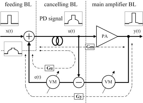
Above
figure shows a simplified block diagram of the RF FBPD. The system consists of three blocks;
`feeding block', `cancelling block', and `main amplifier block'.
In the cancelling block, the error signal of the amplifier, e(t)
is extracted from the main amplifier output, y(t) by eliminating
the estimated input signal component to the amplifier, u(t). That
is, the predistortion signal which is suitable for linearizing the
main amplifier is extracted. The predistorted signal is fed back
to the input of the main amplifier by the feeding block. The
cancelling loop is similar to the feedforward main signal
cancelling loop. In the frequency domain, the input signal X,
the predistorted signal U, the predistortion signal E, the
distortion of the amplifier Xd, the error of the
detection loop Xf, and the output signal Y of the FBPD
system are
expressed as
where Gu is the complex signal gain of the cancellation block, Gm is the complex signal gain(open loop) gain of the main
forward path, and Gy is the complex signal gain of the feedback
path. The capital letters denote frequency-domain representation of each signal.
From the above equations, U and Y are given by
The 1st term is the fundamental signal amplification,
the 2nd term is the IM signal cancellation, and the 3rd term is
the feedback loop distortion. The approximation clearly shows
the feedback operation of the system; the overall gain of the
FBPD, GPD is determined by the feedback loop gain only,
i.e., 1/Gy, which is independent of the amplifier gain
fluctuation due to temperature variation, etc. The (1-Gu)
term indicates that the predistortion signal is extracted from the
loop and is injected into the main amplifier. For accurate
predistortion, Gu should be adjusted close to the 1. The IM
component is further suppressed by a factor of closed loop gain
GyGm due to the negative feedback operation.
Therefore, the system is named FBPD. However, the detector circuit
error Xf is forwarded to the output, and significant
improvements of the error are not effected compared to the
conventional digital PD algorithm.
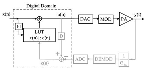
The structure of the proposed digital FBPD is
the same as analog feedback except that the feedback signal e(t)
in the cancellation loop constructs a LUT in the digital domain,
and the gain factors, Gu and Gy, of the signal
cancelling and feedback paths are adjusted by the digital signal
processor (DSP) instead of using vector modulators (VMs) in the RF
domain. The predistortion signal is extracted directly from the
LUT, which has been updated using the error signal extracted at
the signal cancellation loop beforehand. Thus, the time delay
through the loop is eliminated, and the bandwidth limitation does
not exist. The oscillation tendency of the feedback circuit can be
suppressed easily by digital control of the feedback component.
Moreover, the abundant advantages of the FBPD circuit mentioned
above can be utilized for the linearization. The distortion
correction of the PD is carried out by the digital PD and further
enhanced by the feedback linearization. Another merit of the
digital FBPD is rapid convergence due to efficient PD signal
extraction by the feedback circuit. And the initial condition for
the PD signal has little effect on the convergence behavior.
2.2
Equivalent Models and Adaptive Alogrithms
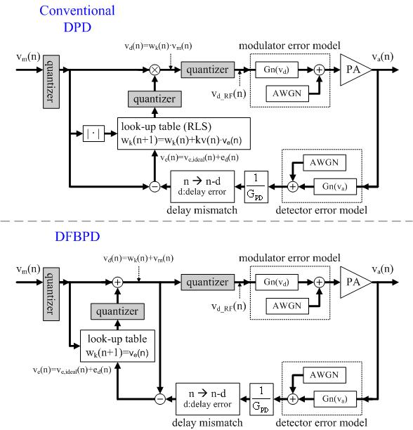
Above
figures show the equivalent models of conventional
digital PD and the proposed DFBPD. Each model includes several error
models for the detector, a modulator, a delay mismatch block, a
predistortion signal error, and quantizer blocks to test performance
and check tolerances under various conditions. As shown in figures,
the additive white Gaussian noise (AWGN) and 3rd-order nonlinear
elements Gn(·) are used as error sources for the detection and
modulation parts, modeling the thermal noise and mixer nonlinearity,
respectively. The delay mismatch blocks are added to represent the
overall loop delay mismatches. Also, the quantizer blocks are
included to analyze the quantization errors of the source signal,
LUT, and PD output.
The digital PD employs the recurisive least-square (RLS) adaptive
algorithm to extract the error signal to provide fast
convergence. The extracted error signal is stored
into a LUT, and a stored value multiplies the input signal to
generate a PD signal. For the FBPD, we can directly extract an
accurate error from the feedback loop (cancellation loop), and the
error signal is stored into the LUT. Then, the stored error signal
is added to the input as a predistortion signal without any loop
delay.
The PD signal generation and the adaptation algorithms of the
digital FBPD are quite different from conventional digital PD. The
RLS adaptive algorithm is initialized by
where a is a
small positive constant, is a K
X 1 vector,
where K is the size of the LUT, and I is the K
X K
identity matrix. Next, for each time, n = 1, 2, ..., computed as
is a K
X 1 vector,
where K is the size of the LUT, and I is the K
X K
identity matrix. Next, for each time, n = 1, 2, ..., computed as

where
λ is the forgetting factor (a scalar value) and
P(n) is a K X K matrix. Both π(n) and Kv(n) are
the K X 1 matrices. The LUT is constructed and updated by
each successive iteration. On the other hand, the DFBPD algorithm
is very simple and expressed as
where vd(n) is the predistorted input signal,
va(n) is the final output signal, and GPD is
the overall PD system gain. The LUT is constructed by this error
signal ve(n).
2.3
Experimental Results
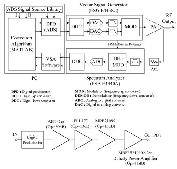
In order to validate the proposed digital FBPD technique, we have
employed the ADS-ESG-VSA connected solution as an experimental setup for quick and exact verification,
and used the Doherty power amplifier (DPA) module shown above figure
with 180-W of peak envelope power (PEP) and 20-W average power for a
single-carrier forward-link WCDMA signal. The main amplifier of the
DPA module consists of two Freescale MRF5S21090 LDMOSFETs, and the
uneven power drive technique is applied to improve the
performance. The signal used is a 2.14-GHz forward
WCDMA signal with a 3.84-MHz of chip rate and 9.8-dB PAR at 0.01%
complementary cumulative distribution function (CCDF), generated
using the 3GPP WCDMA library of ADS. The conventional digital PD and
the proposed digital FBPD have two 256-entry AM/AM and AM/PM LUTs,
which are programmed by MATLAB using the RLS and FBPD algorithms,
respectively.
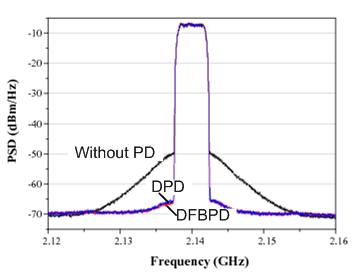
Above figure shows the measured spectra before
and after linearization by the digital PD and FBPD for the WCDMA
signal. The ACLRs at 2.5-MHz offset for the two techniques are
nearly the same, -58 dBc, which is an improvement of 15 dB at an
average output power of 43 dBm. These experimental results
demonstrate that the both predistortion techniques can successfully
compensate for the nonlinear characteristics of the Doherty
amplifier.
3.
Weighted Polynomial Digital Predistortion (DPD) Technique
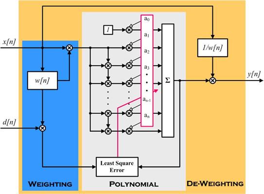
As shown in above
figure, the proposed weighted polynomial
algorithm is consisted of the weighting, polynomial and de-weighting
blocks. The weighting is introduced to get an ideal error function
for the least square fit algorithm. The weighting
function describes the statistical characteristics of the modulation
signal and the harmonic generation property of an amplifier at a
high power level. Then, the weighted polynomial PD signals are
generated by using a polynomial least square fit algorithm. Finally,
the generated PD signals are de-weighted and applied to the PA.
These procedures are iterated using the indirect learning
architecture until we get the linear output.
The least square fit algorithm is employed to optimize the
coefficients with a minimum square error for a
sequential ramp training signal. For the modulated signal, the error
function is not accurate since the occurrence of the data
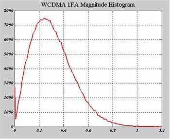
point, i.e. probability density function (p.d.f.) is different. In
case of the forward-link WCDMA signal, the p.d.f. of the amplitude
response has the Rayleigh distribution as shown in below figure.
We can estimate the overall error, which is sum of differences
between modeled responses (yi) and desired responses (di) of
the modulated signal, with the least square fit optimized polynomial
coefficients. The overall error can be calculated by integrating the
product of the average error distribution at each amplitude
(erroravg(x)), which is determined by the least square fit
model, by the Rayleigh p.d.f. as follows:
The non-weighted ramp training signal has an uniform average error
distribution, and it is not the optimum for the minimum overall
error of the WCDMA signal. Therefore, the Rayleigh distribution weighting is applied to the
least square fit error function for the ramp training
signal. Another point is that the PD signal at the peak power region, which
is dominant for harmonic generation, should to be emphasized more
than the other power regions. Therefore, we have implemented an
increasing exponential weight to improve accuracy at the peak power
region and to describe the harmonic generation property accurately as follows:
The above
equation shows that it can represent the harmonic
generation property of an amplifier, and as a becomes large,
the high order terms have more weighting than the low order terms.
As a consequence, the exponential function raises the accuracy at a
higher power region, and a=1 provides a good weighting function.
2.1
Experimental Results
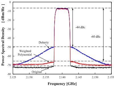
Above
figure shows the measured power spectral densities obtained
using the proposed optimum weighted polynomial algorithm and the
non-weighted polynomial algorithm. The proposed optimum weighting
algorithm could deliver a good ACLR of -60 dBc at an average power
of 43 dBm, which is a cancellation of 16 dB with PAE of about 29%, while the non-weighted polynomial case has a poor ACLR
cancellation of 4 dB at the same average power.
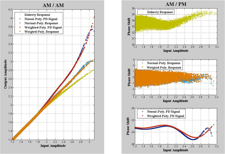
Above
figure shows
AM/AM curves with the optimum weighting algorithm and the
non-weighting case. These results show clearly the improved accuracy
of the optimum weighted polynomial fit.