
1. Introduction to the Doherty Amplifier
The base-station power amplifiers for CDMA applications,such as IS-95 series, CDMA-2000, WCDMA, and so on, generally have a critical system requirement for high linearity, but the efficiency is not specified. General power amplifiers for base stations have a very low efficiency because they must achieve the required high linearity by operating with over 10 dB backed off due to a high peak-to-average ratio (around 10 dB), additional linearization circuits, and complex control circuits.
Today, high efficiency and good linearity have become important figures of merit for power amplifiers in CDMA & WCDMA base stations. The microwave & RF Doherty amplifier is the most promising solution for this use.
2. The conventional Doherty amplifier vs. The proposed Doherty amplifier
The conventional Doherty amplifier was first proposed to improve efficiency using the load modulation of a carrier amplifier through a peaking amplifier attached to a quarter-wave impedance transformer. However, there are some problems that limit the conventioanl Doherty amplifier for use as power amplifiers of commercial wireless communication systems. The only resistive matching method using bulky two sections of quarter-wave transformers has been implemented for the output of the conventional Doherty amplifier and is not the optimum power matching for a complex device impedance. Fig 1. (a) & (b) illustrate equivalent-load networks including a simplified equivalent circuit of active devices at a low-power operation for the conventional Doherty amplifier[see Fig 1. (a)] and the proposed Doherty amplifier[see Fig 1. (b)].
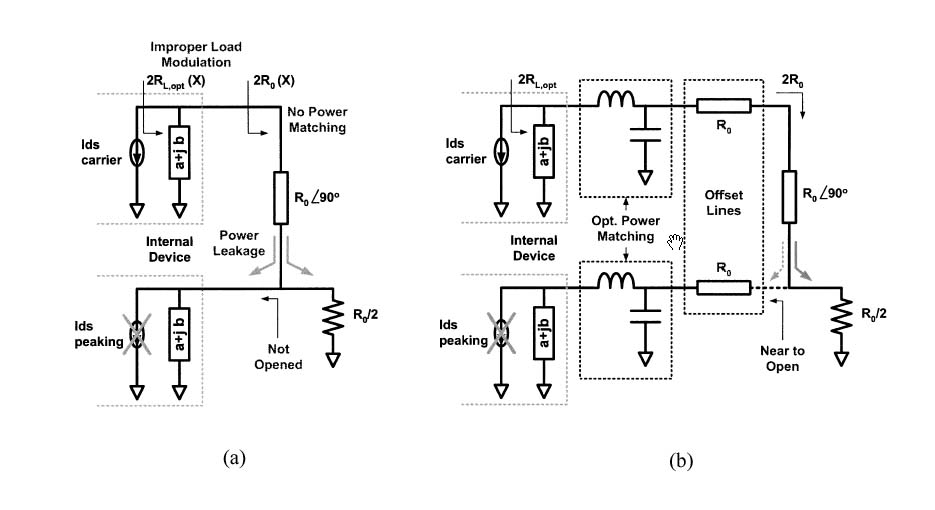
Fig. 1.(a) The conventional Doherty amplifier. (b) The proposed Doherty amplifier.
![]() High Power Amplifier
for CDMA Base Stations Using Doherty Configuration
High Power Amplifier
for CDMA Base Stations Using Doherty Configuration
We have excluded it. Two 2.14GHz high power Doherty amplifiers are implemented using two MRF5S21090 and a MRF5P21180, respectively, and are optimized at 40W for high efficiency and good linearity using IS95 8FA CDMA signal.
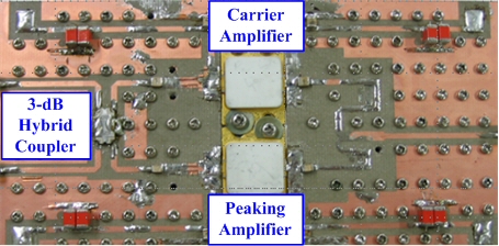
Fig. 2. Implemented 2.14-GHz MRF5P21180 Doherty amplifier .
performance
(a) (b)
Fig. 3. Measured performances of the highly efficienct Doherty and Balaned amplifiers with IS95 8FA CDMA signal. (a) ACLR.(b) Efficiency.
|
|
Gain [dB] |
Efficiency [%] |
ACLR [dBc] |
|
|
-2.25 MHz |
+2.25 MHz |
|||
|
Balanced_21090*2 |
11.16 |
23.6 |
-31.5 |
-31.0 |
|
Doherty_21090*2 |
9.86 |
34.8 |
-31.5 |
-31.3 |
|
Doherty_21180 |
10.3 |
40.0 |
-31.3 |
-31.6 |
TABLE
Measured performance at Pout = 46dBm for IS95A 8FA signal
Fig. 4. Power spectral densities at an output power 46dBm for a IS95A 8FA CDMA signal
These experimental results clearly demonstrate that the microwave Doherty amplifier is a good candidate for power amplifier of CDMA base station application that requires high efficiency as well as good linearity .
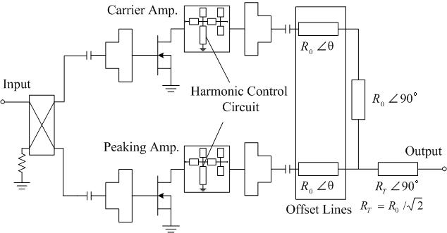
3. N way Doherty Amplifier
We propose a new N-way generalization method of the microwave Doherty amplifier to further enhance output performances.
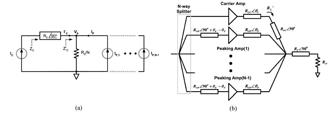
Fig. 1.(a) Load modulation diagram. (b) N-way schematic diagram.
Load modulation can be analyzed using ideal current sources. Fig 1. (a) shows an operational diagram to analyze the load modulation characteristics for the N-way Doherty amplifier. A schematic diagram of the N-way Doherty amplifier is shown in Fig 1. (b). The N-way Doherty amplifier is composed of an N-way power splitter/combiner, fully power matched amplifiers for the carrier and peaking amplifiers, offset lines, and quarter-wave transformers.
![]() Low Power Amplifier based on
N-Way Doherty Amplifier
Low Power Amplifier based on
N-Way Doherty Amplifier
The basic amplifier cell has been designed using Motorola’s 4 W-PEP silicon LDMOSFET for the carrier and peaking amplifiers.
performance
(a) (b)
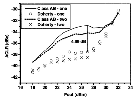
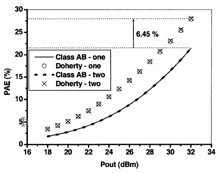
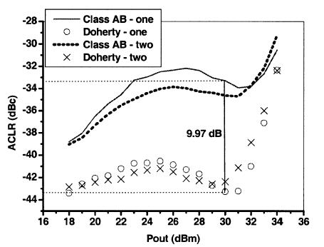
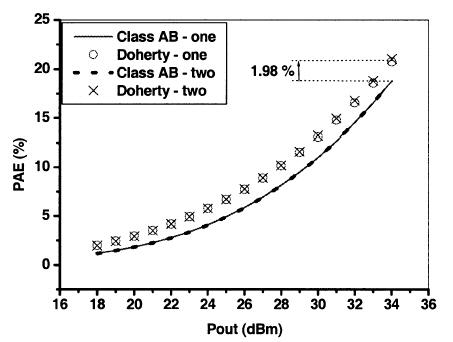
Fig. 2. Measured performances of the two-way Doherty and class-AB amplifiers with one- and two-carrier down-link WCDMA signals. (a) ACLRs.(b) PAEs.
(a) (b)
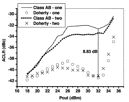
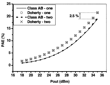
Fig. 3. Measured performances of the three-way Doherty and class-AB amplifiers with one- and two-carrier down-link WCDMA signals. (a) ACLRs.(b) PAEs.
(a) (b)
Fig. 4. Measured performances of the four-way Doherty and class-AB amplifiers with one- and two-carrier down-link WCDMA signals. (a) ACLRs.(b) PAEs.
![]() High Power Amplifier based on
3-Way Doherty Amplifier with Predistorter
High Power Amplifier based on
3-Way Doherty Amplifier with Predistorter
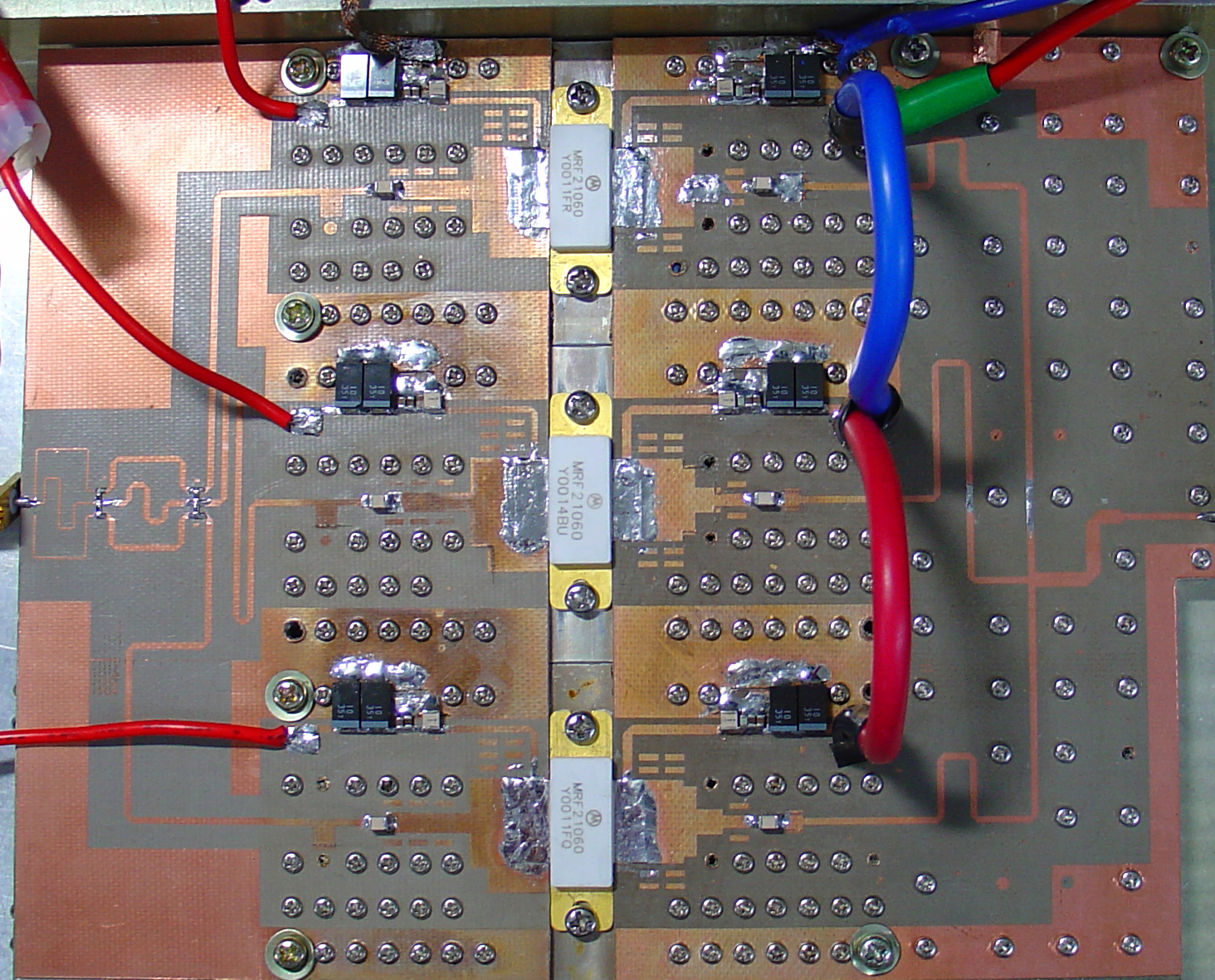
Fig. 5. Implemented 2.14-GHz 3-way Doherty amplifier .
performance
(a) (b)
Fig. 6. Measured performances of the 3-way Doherty and class-AB amplifiers with one- and two-carrier down-link WCDMA signals. (a) one-carrier.(b) two-carrier.
|
|
WCDMA 1FA |
WCDMA 2FA ( spacing = 10MHz) |
||
|
ACLR [dBc] |
PAE [%] |
ACLR [dBc] |
PAE [%] |
|
|
Class AB |
-40 |
8.2 |
-40.6 |
-8.2 |
|
Doherty |
-50.1 |
11.1 |
-47.4 |
10.3 |
|
Doherty with PD |
-51 |
11.1 |
-49.1 |
10.3 |
TABLE
Measured performance at Pout = 40dBm for WCDMA signal
Fig. 7. Power spectral densities at an output power 40dBm for a WCDMA 2FA ( spacing =10MHz ).
The experimental results show that the 3-way Doherty amplifier with predistorter is a good alternative for a cheap repeater system that requires less stringent linearity requirement and small power handling than a base station system.
4. Bias Adaptation of Doherty Amplifier
Many research works have tried to realize the Doherty amplifier using a simple bias arrangement for the carrier and peaking amplifiers. Gate bias adaptation of the Doherty amplifier can much improve its performances. The structure for the gate bias adaptation of the Doherty amplifier is shown below.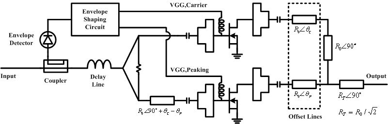
Fig 1. Bias adaptation Doherty amplifier schematic diagram.
performance
For the experiments, a 2.14GHz Doherty amplifier have been implemented using 4 watt PEP LDMOSFETs. The gate control biases of the Doherty amplifier have been optimized for the maximum power added efficiency(PAE) at –30dBc ACLR. The tests have been performed using a forward-link WCDMA signal and the performances of the amplifier have been compared with those of class AB and conventional Doherty amplifiers. The measured performance is shown below.
|
Bias Condition |
Output Power [dBm] |
PAE [%] |
|
Class AB |
31.3 |
24.5 |
|
Conventional Doherty |
32.1 |
28.1 |
|
Adaptive Doherty |
33.5 |
41.0 |
TABLE
Measured performance at ACLR = -30dBc for WCDMA signal
The adaptive bias controlled Doherty amplifier has PAE of 41 % with 33.5 dBm average output power at –30 dBc ACLR, which is an improvement of 16.65 % and 12.9 % in efficiency and 2.2 dB and 1.4 dB in output power relative to the class AB and conventional Doherty amplifiers at the same ACLR level. These experimental results clearly demonstrate that the adaptively controlled Doherty amplifier is the best performing amplifier for the base station power application that requires high efficiency as well as good linearity.
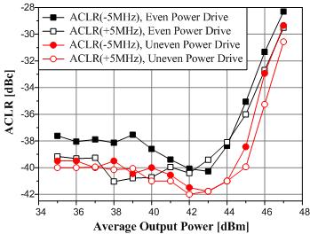
5. Uneven 2-way Doherty amplifier
We have proposed advanced design methods of Doherty amplifier for high efficiency base station power amplifiers with wide bandwidth. First, we develop Doherty amplifier with uneven power drive which is provided more input power to the peaking cell than the carrier cell for full power operation and appropriate load modulation. Second, we optimize the matching circuits of the carrier and peaking cells individually to enhance the linearity and efficiency. Third, we optimize the bias circuit to solve an asymmetric ACLR characteristics for wideband signals such as WCDMA 4FA.
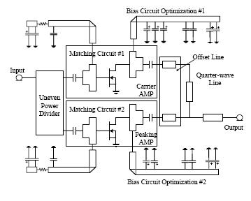
Fig 1. Uneven 2-way Doherty amplifier schematic diagram.
performance
6. Uneven 3 - way Doherty Amplifier
We have demonstrated a high linear 3-way Doherty amplifier by applying uneven power drive and optimizing the peaking biases and load impedances. The amplifier has been implemented at 2.14 GHz using 190W PEP LD-MOSFETs.
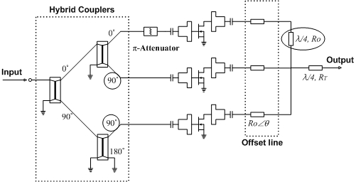
Fig. 1. Structure of the 3-way Doherty amplifier with uneven power drive.
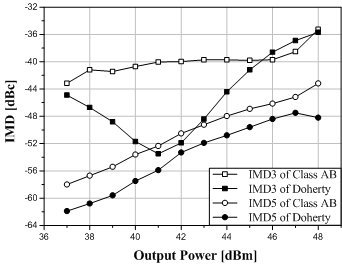
The linearity enhancement of the 2-way Doherty amplifier has been incorporated with the dominant cancellation of the third-order intermodulation(IM3). The 3-way Doherty amplifier with even power drive has been optimized for the IM3 cancellation only because of the identical operation of the two peaking amplifiers with equal quiescent bias point. In this work, we have optimized the two peaking amplifier's gate biases and load networks separately to cancel not only IM3 but also IM5 cancellations.
performance
(a) (b)
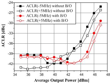
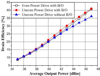
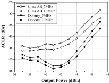
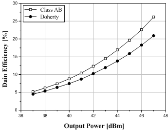
Fig. 2. (a) ACLR performances and (b) Drain efficiencies of the Doherty and class AB amplifiers
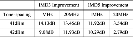
<TABLE> IMD3 and IMD5 improvements for the two tone signal
(a) (b)
Fig. 3. (a) ACLR performances and (b) Drain efficiencies of the Doherty and class AB amplifiers
|
|
WCDMA 4FA |
||
|
ACLR @ 5 MHz [dBc] |
ACLR @ 10 MHz [dBc] |
DE [%] |
|
|
Class AB |
-42.86 |
-44.77 |
12.3 |
|
Doherty |
-52.5 |
-53.4 |
10.2 |
<TABLE> Measured performance at Pout = 42dBm for WCDMA signal
In the two-tone test, IMD3 has been improved more than 9 dB compared to the class AB amplifier with IMD5 enhancement of 10 dB. The ACLRs at 5 MHz and 10 MHz offsets are -52.5 dBc, -53.4 dBc, respectively, which are improved by about 10 dB compared to the class AB amplifier while maintaining drain efficiency.
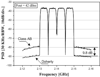
Fig. 4. Power spectral densities at 42 dBm for the forward-link WCDMA 4-carrier signal
These experimental results show clearly that the proposed Doherty amplifier has a superior linearity than any other general HPA without using any extra linearization circuits. Therefore, it is expected to be very useful for the medium power HPA that requires high linearity.
7. Saturation Doherty amplifier
To improve the efficiency more than the previous Doherty amplifier, we have employed the switching power amplifier with harmonic control circuit for the Doherty amplifier. Due to the harmonic generation by the control circuit, the Doherty amplifier hs square-wave current and half-sinusoidal voltage signals (inverse-class F). These transformed waveforms cause the saturation operation so that the Doherty amplifier hs higher efficiency than the previous one.
Load Line Analysis of Saturation Doherty amplifier
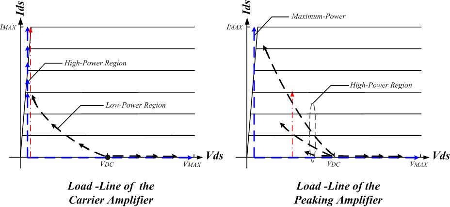
The carrier amplifier can not reach to the saturation state until the peaking amplifier is turn-on due to insufficient drive. Thus, the load lines represent a slightly elliptical lines as shown in above figure (left). At the input drive above the turn-on voltage of the peaking amplifier, the carrier amplifier gets into the saturation state, and the load line draws the “L” curve. This state illustrates that the amplifier has a square-wave current and half-sinusoidal voltage signals. At a high power region, because the load impedances of the both amplifiers decrease, the load lines of the carrier amplifier move up while maintaining the “L” curves as shown in above figure (left). Due to the proper load modulation, the current and voltage swings of the peaking amplifier increase in proportion to the power level and reach to the maximum square-wave current/half-sinusoidal voltage waveforms at the maximum power level. The load lines of the peaking amplifier represent slightly elliptical lines until the maximum power level, and the load line draws the “L” curve at the maximum power level as shown inabove figure (right). The peaking amplifier represents the saturation state only at the maximum power.
performance
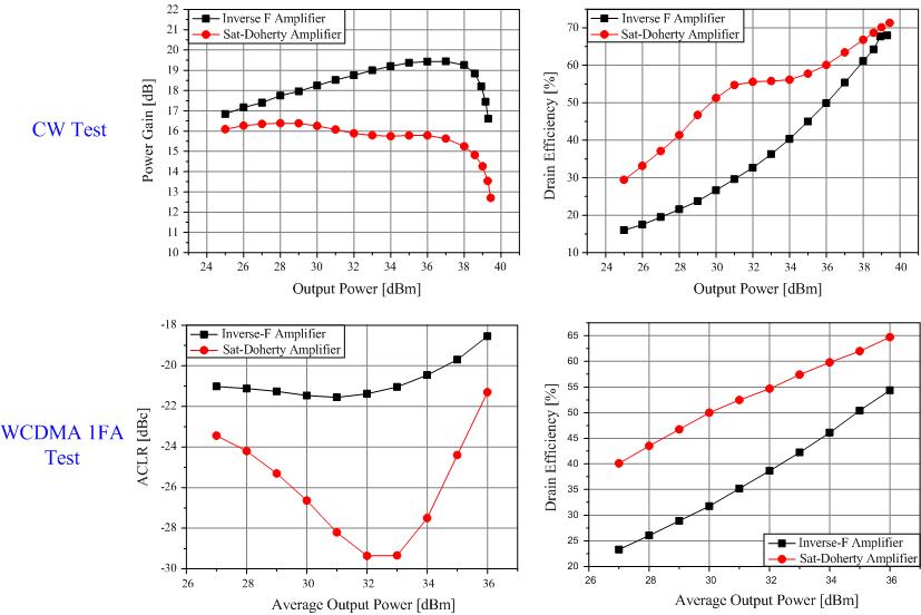
Above figures show the measured ACLRs of the saturation Doherty amplifier and the inverse class F amplifier at an offset of 2.5-MHz for a 1-GHz forward-link WCDMA signal. In comparison with the inverse class F amplifier, the Doherty amplifier delivers a significantly improved ACLR performance, –29.4 dBc which is an improvement of 8 dB at the average output power of 32 dBm, and shows the drain efficiencies of the saturation Doherty amplifier and the inverse class F amplifier for the WCDMA signal. The drain efficiency of the Doherty amplifier is improved over a broad average output power levels and enhanced by 16% at an average output power of 32 dBm. Moreover, the drain efficiency of the saturation Doherty amplifier has a lot higher than that of the previous Doherty amplifier.
8. 3.5GHz Doherty amplifier
We have implemented the Doherty amplifier using GaN HEMT for 3.5-GHz IEEE 802.16-2004 WiMAX applications, which is the OFDM waveform 64-QAM-3/4, 8 burst, 28 MHz channel bandwidth and a PAR of 8.87 dB at 0.01% for the probability on Complementary Cumulative Distribution Function (CCDF). Below figure shows a photograph of the fabricated Doherty amplifier, which is built using Eudyna P3dB 90-W EGN35A090IV GaN HEMT. For the even power drive, we have used an Anaren 1M703 (3 dB directional coupler).The individual matchings of the carrier and peaking amplifiers are further optimized to achieve a high linearity and efficiency at an average output power of 43 dBm. In the experiments, the optimum offset line is 42.88◦, and the quiescent biases of the carrier and peaking amplifiers are set to Vgs,C = –1.069 V (Ids,q = 750 mA) and Vgs,P = –3.402 V at Vdd = 50 V, respectively. The biases are selected to cancel maximally the in-band error distortions.
performance
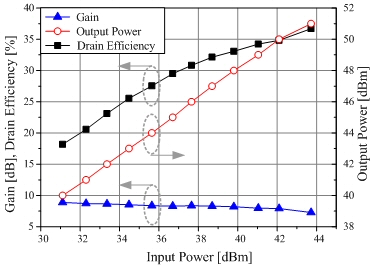
Above figure shows the measured continuous wave (CW) characteristics of the Doherty amplifier. The amplifier can handle a 51 dBm of P1dB and has been designed at an average output power of 43 dBm, 8 dB backedoff from the P1dB.
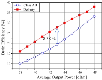
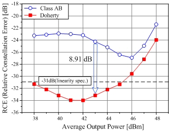
Among the above figures, left one shows the drain efficiencies of the Doherty and class AB amplifiers for the modulation signal. The drain efficiency of the Doherty amplifier is 27.8% and improved by about 8% at the average output power of 43 dBm. Also, right one shows the RCE performances of the Doherty and class AB amplifiers. In comparison with the class AB amplifier, the Doherty amplifier delivers a significantly improved RCE performance, –33.17 dB which is an enhancement of 8.91 dB at the average output power. This result represents that the gm3 cancellation between the carrier and peaking amplifiers can improve not only out-of-band error but also in-band error.
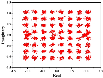
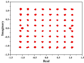
Above figures show the signal constellation diagram of the implemented Doherty and class AB amplifiers. In comparison with the signal constellation diagram of the class AB amplifier, we can recognize the diagram of the Doherty amplifier is clearer, which means the Doherty amplifier can amplify the signal more linearly. The linearity specification for the modulation signal is –31 dB of RCE. From the measured results, we can see that the Doherty amplifier can satisfy the linearity specification of the WiMAX applications. The results show clearly that the Doherty amplifier is very attractive for the 3.5-GHz WiMAX applications since the amplifier can deliver the excellent linearity with good efficiency without using any special linearization techniques.
9. Gate Bias Control
It is well known that the linearity improvement method of the Doherty amplifier is the IM3 cancellation of the carrier and peaking amplifiers. When the IM3 characteristics of the amplifiers are perfectly satisfied with the (1), the IM3 power at the output stage is cancelled out
 (1).
(1).
Because the IM3 magnitude and phase of each amplifier are functions of the gate bias and power level, it is difficult to reduce the IM3 over broad power levels for the fixed gate bias. In order to optimize the cancellations over broad average power ranges, we have selected the proper gate biases of the amplifiers at each input power level through the two-tone test. Fig. 1 shows the measured IMD3 and IMD5 characteristics when the gate biases of the carrier and peaking amplifier are optimized to cancel the harmonics maximally. Fig. 2 shows the fixed and optimized gate bias conditions of the carrier and peaking amplifiers. When both carrier and peaking amplifiers are “ON” state at the input power of 22 dBm, the Doherty amplifier start to cancel the IM3. By adjusting the gate biases to the optimum values for each power level, we could obtain more linear characteristic over the broader power range.
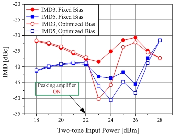
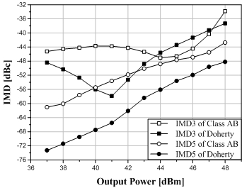
Fig. 1. IMD3 and IMD5 of the Doherty amplifier.
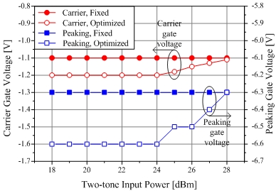
Fig. 2. Fixed and optimized gate biases of the carrier and peaking amplifiers.
To validate the envelope tracking for 802.16d signal, we have used the test bench in Fig. 3, which consists of advanced design system (ADS) as an I and Q data source, MATLAB as a digital signal processor (DSP) for shaping the gate bias, ESG E4438C as a modulator for 802.16d RF signal source, and PSG E8267D as a digital-analog converter (DAC) for the shaped gate bias source. Fig. 4 shows the gate biases, which are shaped based on Fig. 2, of the amplifiers and envelope signal for 802.16d signal at an average output power of 35 dBm. Table I shows the measured results of the class-AB and Doherty with and without envelope tracking. In comparison with the fixed gate bias Doherty amplifier, the amplifier with the envelope tracking delivers a significantly improved RCE performance of -35.3 dB, which is an enhancement of about 4.3 dB at an average output power of 35 dBm, while the RCE of the Doherty without gate bias control is improved by about 3.3 dB compared with the class-AB. The PAEs of the Doherty amplifiers with and without gate bias control are about 30% and enhanced by about 12% compared with class-AB. Although the envelope tracking technique is intended to extend the IM3 cancellation power range for linearity improvement, the PAE is enhanced slightly because of the lower gate biases for the carrier and peaking amplifiers compared to the fixed gate bias Doherty amplifier. Fig. 5(a) and (b) show the measured signal constellation diagram for the fixed gate bias and envelope tracking Doherty amplifiers. In comparison with the signal constellation diagram of the Doherty amplifier without envelope tracking, we can recognize the diagram of the amplifier with gate bias control is clearer, which means the proposed Doherty amplifier can amplify the signal more linearly.
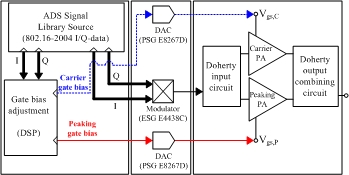
Fig. 3. Experimental setup for the envelope tracking.
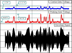
Fig. 4. Measured gate biases of the carrier and peaking amplifiers and envelope signal.
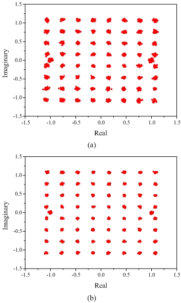
Fig. 5. Measured signal constellation diagram of 802.16d at an average output power of 35 dBm: (a) Fixed gate bias. (b) Controlled gate bias.
Table I. Summary of the measured performance at an average output power of 35 dBm for 802.16d signal
|
|
Gain [dB] |
PAE [%] |
RCE [dB] |
|
Class AB |
14.54 |
18.38 |
-27.7 |
|
Doherty (Fixed bias) |
12.65 |
29.76 |
-31 |
|
Doherty (Envelope tracking) |
12.46 |
30.44 |
-35.3 |
10. Wideband Doherty
Highly efficient linear power amplifier with wideband characteristic is a key component in WiMAX systems, which have a large signal bandwidth and PAPR.We have fabricated a wideband Doherty amplifier using Eudyna 10-W PEP EGN010MK GaN HEMTs, because the GaN HEMT is the most promising device due to the high breakdown voltage, high current density, relatively small knee voltage, and small output capacitance. The wideband Doherty amplifier is designed at an average output power of 34 dBm, backed-off about 10 dB from the P1dB of 44 dBm. The individual matchings of the carrier and peaking amplifiers are further optimized to achieve a high linearity, efficiency, and wideband characteristics. In the experiments, the quiescent biases of the carrier and peaking amplifiers are set to Vgs,c=-1.11 V (Ids,q=90 mA) and Vgs,p=-6.3 V at Vdd=50 V, respectively. The biases are selected to maximally cancel the in-band error distortions. The implemented amplifier has been tested using twoWiMAX signals such as 802.16d with 28 MHz signal bandwidth and PAPR of 8.87 dB and 802.16e with 10 MHz signal bandwidth and PAPR of 10.98 dB. Fig. 1 shows the measured performances of the Doherty amplifier for the two WiMAX signals at the center frequency of 2.345 GHz. Up to the average output power of 35 dBm, the amplifier is met with the linearity specifications of both applications, which are -31 dB and -30 dB of RCE for 802.16d and 802.16e, respectively, while the PAEs are about 30%. Fig. 2 shows the measured wideband performances of the amplifier at an average output power of 34 dBm for the power gain, PAE, and RCE. In the 90 MHz bandwidth, the variations of the gain and PAE are about 0.35 dB and 2%, respectively, and the linearity specifications are satisfied.
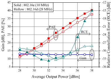
Fig. 1. Gain, PAE, and RCE performances of the Doherty amplifier for 802.16d and 802.16e signals at 2.345 GHz.
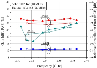
Fig. 2. Gain, PAE, and RCE performances of the Doherty amplifier for 802.16d and 802.16e signals across the 90 MHz bandwidth at an average output power of 34 dBm.
Reference
[1] Y. Yang, J. Yi, Y.Y. Woo, and B. Kim, "Optimum Design for Linearity and Efficiency of Microwave Doherty Amplifier Using a New Load Matching Technique," Microwave Journal, vol. 44, No. 12, pp. 20-36, Dec. 2001.
[4] B. Kim, Y. Yang, J. Yi, Y. Y. Woo, and J. Cha, "Optimum Design of Microwave Doherty Amplifier for Linearity and Efficiency," invited paper, PIERS, Singapore, Jan., 2003.
[5] Y. Yang, J. Cha, B. Shin, and B. Kim, "A Fully Matched N-way Doherty Amplifier with Optimized Linearity," IEEE Trans. Microwave Theory Tech., Vol. 51, No. 3, pp. 986-993, Mar., 2003.
[6] Y. Yang, J. Cha, B. Shin, and B. Kim, "A Microwave Doherty Amplifier Employing Envelope Tracking Technique for High Efficiency and Linearity," IEEE Microwave and Wireless Components Letters, Vol. 13, No. 9, Sep. 2003.
[7] J. Cha, Y. Yang, B. Shin, and B. Kim, "An Adaptive Bias Controlled Power Amplifier with a Load-Modulated Combining Scheme for High Efficiency and Linearity," IEEE MTT-S Int. Microwave Sympo., Philadelphia, Vol. 1, pp. 81-84, June 2003.
[8] J. Cha, J. Kim, B. Kim, J. S. Lee, and S. H. Kim, "Highly Efficient Power Amplifier for CDMA Base Stations Using Doherty Configuration", IEEE MTT-S Int. Microwave Symp., Fort Worth,Texas, pp. 533 - 536, 6-11 June, 2004.
[9] B. Shin, J. Cha, J. Kim, Y.Y. Woo, J. Yi, and B. Kim, "Linear Power Amplifier based on 3-Way Doherty Amplifier with Predistorter", IEEE MTT-S Int. Microwave Symp., Fort Worth,Texas, pp. 2027 - 2030, 6-11 June, 2004.
[10] Bumman Kim, "Microwave Doherty Amplifier for High Linearity and Efficiency", invited talk, IEEE MTT-S Int. Microwave Symp. Workshop, Fort Worth,Texas, June, 2004.
[11] Bumman Kim, Jeonghyeon Cha, Bumjae Shin, Jangheon Kim, and Ildu Kim, "High Power Microwave Doherty Amplifier for Linearity and Efficiency Enhancements," invited talk, Asia-Pacific Microwave Conference(APMC 2004), Deli, India, 15-18 Dec., 2004.
[12] Ildu Kim, Jeonghyeon Cha, Sungchul Hong, Jangheon Kim, YoungYun Woo, Cheon seok Park, and Bumman Kim, “Highly Linear Three-Way Doherty Amplifier with Uneven Power Drive for Repeater System”, IEEE Microwave and Wireless Component Letters, Vol.16, No.4, pp.176-178, Apr., 2006.
[13] Jangheon Kim, Jeonghyeon Cha, Ildu Kim, and Bumman Kim "Optimum Operation of Asymmetrical-Cells-Based Linear Doherty Power Amplifiers-Uneven Power Drive and Power Matching," IEEE Trans. Microwave Theory Tech., Vol. 53, No. 5, pp. 1802 - 1809, May, 2005.
[14] Ildu Kim, Jangheon Kim, Jeonghyeon Cha, YoungYun Woo, Sungchul Hong, and Bumman Kim, “The linearity and efficiency improvement of 3-way Doherty amplifier with uneven power drive,” International Technical Conference on Circuits/Systems, Computers and Communications, Jeju, Korea, pp. 369 - 370, July, 2005.
[15] Jangheon Kim, Jeonghyeon Cha, Ildu Kim, Bumman Kim, Sang Yeon Noh, and Cheon Seok Park, "Advanced Design Methods of Doherty Amplifier for Wide Bandwidth, High Efficiency Base Station Power Amplifiers," 35th European Microwave Conference, Paris, France, pp. 963 - 966, Oct., 2005.
[16] Bumman Kim, Jangheon Kim, and Jeonghyeon Cha, "The Doherty Power Amplifier Technique for Base Station Application," Invited Keynote Speech at 2006 IN MMIC, Aveiro, Portugal, Jan. 30, 2006.